Product Description
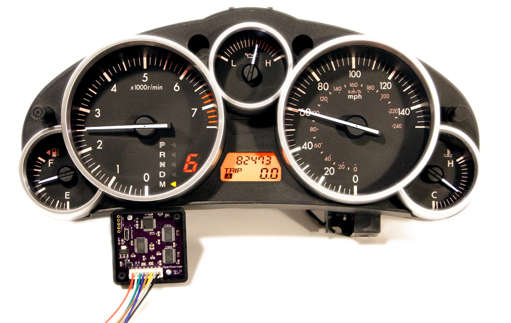
The NC Cluster Commander is a circuit used to translate the GM CAN bus data stream (commonly referred to as GMLAN) to the Mazda MX5 instrument cluster for LFX, LS2, and LS3 swaps.
It uses two separate CAN bus interfaces to translate the data between the two networks. The interface that's connected to the GM side only listens, meaning that you can perform ECM reflashes via HP Tuners or EFI Live without needing to disconnect the Cluster Commander from the network. Currently E39 (2012+), E38 (2006-2009), and E38 2010+ ECM's are supported. E67 ECM's use the same encoding as the 2006-2009 E38.
The Cluster Commander translates the Tachometer, Odometer, Speedometer, Check Engine Lamp, Oil, Coolant gauges as well as the PRNDM1-6 gear selector in an Automatic Cluster.
Features
- Check Engine Light - Translates the GM's MIL lamp wire to be CAN bus controlled.
- Speedometer Tuning - Speed is read via the GM ECM, and can be adjusted without needing HPTuners or EFI Live.
- Tachometer Scaling - Want to run a differently scaled Tachometer face? Now you can.
- Odometer Tuning - Similarly, can improve odometer accuracy without needing a ECM reflash.
- Voltage Monitoring - Will turn on the Battery Lamp if voltage is below a threshold for more than 3 seconds (Default: 12.6v)
- Oil Pressure Table - User editable table to make sure your oil pressure is good everywhere.
- Coolant Thresholds - User settable Low/Medium/High thresholds (Default: 160°F and 220°F) .
- Reverse Light Output - For Automatics - Use a relay to drive the backup lights without needing a GM BCM.
- Power Retractable Hardtop - Now functional in Automatics and Manuals.
- Updatable Firmware - Any bugs that show up can be fixed with a reflash.
OEM Limitations
There are a few limitations to be aware of with the Mazda cluster - none of these should be any surprise, but I thought it best to mention them.
- Oil pressure gauge movement is fake. Position is based on RPM and Coolant temp, but the input is an on/off signal.
- Coolant gauge is similarly fake. It has a Low/Medium/High setting, and is very slow to react.
- Traction Control System, Dynamic Stability Control, Tire Pressure Management System, Anti Lock Brakes, and Security Warning Lights require the stock engine in working condition. The lamps are disabled for a clean look.
- NC2/3 Realtime MPG and outside temperature are currently unavailable (may be able to get working in a future firmware release).
Installation
Before installing make sure to read through the instructions thoroughly. Wiring is roughly as difficult as installing an aftermarket stereo - I made these installation instructions as verbose as possible, so don't be intimidated. If you have any questions or need any clarification, please contact me. I try and answer emails within 24 hours.
Pre-Wiring checklist
Before wiring the module permanently in the car it's useful to perform the software setup if you're planning on using anything but default values, to verify USB connectivity and verify the Oil Pressure Table.
Disconnect the battery.
The most convenient place to install the cluster commander is behind the cluster hood itself. To gain access, you'll need to remove the steering column trim (three screws from the bottom side), then remove the gauge hood (held in place by four plastic pins - be careful to lift directly upwards). The instrument cluster is held in place with three screws and a clip that holds the wiring in place. To free the harness, twist the clip 90° degrees and then remove the two connectors from the rear of the cluster by depressing the connector tab and pulling. You'll need to run three wires from the GM ECM to this location - two for GM CAN and one for the check engine lamp.
There are two connectors on the back of the cluster - a large one on the right side and a smaller one on the left. On the smaller one, strip back a 4-6 inches the harness tape to expose the wires. Be very careful to avoid nicking any wires. We won't be touching any of the wires from the larger connector, so leave it alone.
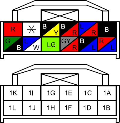
| CC Harness | Function | Pin | Wire Color |
| Red | Switched 12v | 1G | Black/Yellow |
| White | MIL Input | From ECM | Brown/White |
| Green | Oil Gauge Output | 1H | Light Green |
| Blue | CAN bus High | 1J | Blue/White |
| Brown | CAN bus Low | 1L | Green/Black |
| Yellow | GM CAN bus High | From ECM | Tan/Black |
| Gray | GM CAN bus Low | From ECM | Tan |
| Black | Ground | 1A | Black |
There are 8 wires to connect - A pair of CAN wires for the Mazda and GM side (each), the oil pressure switch to the instrument cluster, and the Malfunction Indication Lamp (MIL/Check Engine) from the ECM. GM Canbus wires can be extended from the OBDII Port (if already wired to inside the cabin). The MIL lamp wire will need to be extended to the dash, check your ECM pinout for details.
Three of the wires - Oil Pressure, CAN High and CAN Low are going to be cut and spliced into the circuit - the wires that run to the body side of the harness will be left disconnected. Cut the wire far enough away from the connector leave enough space to comfortably fit a crimp tool / pair of pliers. The CAN bus wires can be untwisted to ease crimping. Wrap the disconnected CAN bus High, Low, and Oil Pressure wires with some electrical tape / heatshrink to prevent them from shorting.
Power and Ground (1A and 1G) will be tapped to provide power to the circuit and instrument cluster. If you're using a 18ga butt splice, cut, strip and twist three wires together into one side of the crimp to tap. If using the included 3M Scotchlock connectors, use all three holes to terminate and tap.
The circuit enclosure box is built with handles that make it easily zip-tied out of the way behind the gauge hood. It's recommended to leave the gauge hood and column trim off until everything is verified to be working.
PRHT and ABS Considerations
Before the Power Retractable HardTop will function it requires knowing that you're in Neutral/Park. Cluster Commander can provide this information, but the "standard" method of wiring only extends the CanBus network to the cluster itself. You'll need to extend a pair of wires from the cluster to the PRHT module located behind the drivers seat. (Note: currently untested - but should be available in an upcoming firmware update)
ABS is best retained by keeping the stock Mazda ECM connected to the rest of the network - except for the instrument cluster. Leaving the instrument cluster networked with the Cluster Commander and ECM will cause cluster confusion.
ECM Source
Three wires are needed from the ECM - the CAN bus pair and the Check Engine Light (MIL). The CAN bus can be sourced and extended from the OBDII plug if more convenient than running more wires from the engine bay.
E38
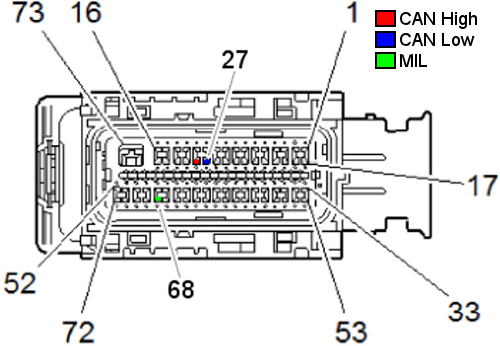
The E38 has two connectors on the ECM, Black and Gray. All three wires we're looking for are in the Black connector.
| Function | Position | Wire |
| CAN High | 28 | Tan/Black |
| CAN Low | 27 | Tan |
| MIL | 68 | Brown/White |
E39
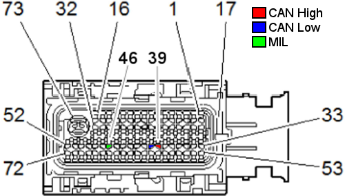
The E39 has three connectors to the ECM - Blue, Black, and Gray. All three wires we're looking for are in the Blue connector.
| Function | Position | Wire |
| CAN High | 39 | Tan/Black |
| CAN Low | 40 | Tan |
| MIL | 46 | Brown/White |
OBDII Connector
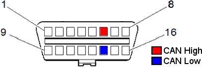
You can also extend the CAN bus wires from the GM OBDII connector - this orientation is looking at the connector face.
Wiring
Scotchlock vs. Crimp vs. Solder in automotive applications is a long debated topic. In my own experience I will say that I prefer a good crimp over a crappy solder, and shame upon anyone that strips and twists wires together with electrical tape. Since the wires in the OEM cluster are thin 22awg wires - I used to include 3M Scotchlock connectors, but now recommend stripping, twisting the wires together, and crimping them together with a single ended crimp connector. CAN bus is very resilient to noise and well suited in an automotive environment - while twisting the wire pair together does help with signal quality (especially inside a bulkhead connector, where crosstalk is at a prime) it isn't necessary for the shorter lengths we'll the patching into.
Software Setup
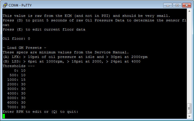
Cluster Commander does not require any additional setup to work - it's already populated with default values for that work well - and I try and set it up with the proper firmware values before the unit is shipped out. But for those that want ultimate control of their cluster I made everything adjustable. The defaults are set for the LFX - the only major difference in settings from the LFX and the LSx engine is the oil pressure requirements. LFX spec is 10psi at idle, 30psi at 2,000 RPM. LS3 spec is 6psi at 1,000 RPM, 18psi at 2,000 RPM, 24psi at 4,000 RPM. By default, the more stringent LFX oil spec is used to control the oil pressure gauge. Assuming your Speedometer and Odometer settings from your ECM are good, no further setup is required.
For the E38 ECM, there are two different GMLAN encoding methods. The later 2010+ E38 uses the same encoding scheme as the E39. 2006-2009 E38 uses a different scheme that can be switched to by the menus. When changing the ECM type, make sure you reload default values, or else the odometer will be wildly off. The 2006-2009 E38 only updates the speedometer and odometer once a second as opposed to the E39 that updates 10 times a second. Update speed can be changed with HPTuners and EFI live and is strongly suggested.
Connecting
Remove the two screws on the enclosure - this will expose the micro USB slot.
Serial Port Selection
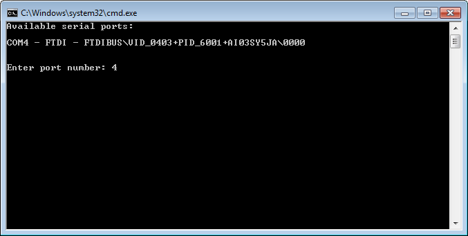
The board uses the FTDI USB to Serial adapter for communication. This is a very common USB Serial converter that most operating systems have drivers built in for - but just in case, drivers can be installed from http://www.ftdichip.com/Drivers/VCP.htm. Once the driver is installed, the next step is to determine which COM port address has been assigned. In windows - go to Control Panel - Device Manager - expand "Ports - COM & LPT" - and take note of any port numbers listed.
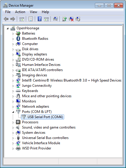
In this example the COM Port is 4. If there are multiple ports listed, unplug the USB cable for 10 seconds and take note of which port disappears, then reconnect. As awkward as it sounds, this is the most reliable method.
Serial Terminal
Now that we know our COM port the next step is to install a Serial Terminal - if you're computer savvy, any serial terminal will do. PuTTY is free application that works extremely well. You can download it here. Once installed, open the application and select "Serial" - Change the Serial Line to the COM port noted above. Baud rate defaults to 9600.

Menus
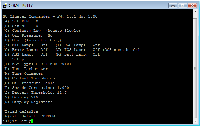
Once connected the Putty will display "GM CAN Init..." until the Enter is hit a few times - then the setup menus will appear. Enter must be hit within 30 seconds of opening Putty.
Most of the menus are straightforward (and options may change as the firmware evolves). Each letter surrounded by a parentheses is a menu option - you must hit Enter to execute a command. If you are connecting to the circuit while the cluster is connected and powered you can manipulate the instrument cluster with the first section. The second section relates to settings that will need to be saved with the "(W)rite to EEPROM" option. Display VIN and Display Registers are used for troubleshooting purposes.
Oil Pressure
The stock Miata oil pressure input is wired to a 10psi pressure switch. Whenever the pressure drops below 10psi, the gauge needle drops to the left peg. The stock gauges movement is affected by coolant temperature and RPM - which make for a very elaborate fabrication of a real mechanical oil pressure gauge. At the lower idle RPM's of the GM engines, it can be difficult to determine if the needle is off the peg - and for track use, lets be frank - nothing can replace a classic mechanical oil gauge.
Cluster Commander extends the functionality of the stock gauge by reading the oil pressure from the ECM and determining if the oil pressure is "good" depending on the RPM range. By default Cluster Commander uses the higher pressure LFX table.
Oil Floor
Almost all electrical sensors have "float" - a little bit of noise in the signal that prevents a static pressure from reading as truly 0 - either from ground offset, wire splicing, or sensor variance. To try and present the most accurate information possible we can subtract this static value from our oil pressure calculation. This is not completely necessary to do - it's often less than half a PSI of oil pressure difference.
With the engine off and cold, enter the Oil Pressure menu and press O and then D. The commander will display the oil pressure directly from the ECM for 5 seconds. Once you have this value, press E and enter it. This value will be subtracted from all oil pressure calculations.
Coolant
The OEM cluster has 3 settings - Low, Medium and High. Here we can set the thresholds for each setting - although the stock temperature thresholds at 160°F and 220°F are fairly universal. GM engines tend to run a little warmer due to their reverse coolant flow and sensor location. On the LFX the cooling fan doesn't kick on (depending on RPM and Torque Zone) until 195°F or 222°F, with both cooling fans going on at 228°F. With the slow movement speed of the needle this should provide ample warning.
Speedometer Calibration
Changed rear tire size? Changed differential ratio after setting up your ECM? Using this menu will help reset your speedometer to be accurate. On a long flat stretch with a good GPS, make note of what your GPS speed is and what your instrument cluster reports. Enter these values into the menu and a simple percentage adjustment will be applied across all incoming VSS speeds from the ECM.
Updating Firmware
All units ship with the most recent firmware available. Firmware Version is displayed on the first line of the main menu. Download the most recent firmware from http://openhoonage.com/firmware and extract the zip to a directory. With the board connected, double click on "RunMe". A window will pop up and display the current com ports - select the one for the Cluster Commander and hit enter.
After hitting enter the flash process will commence. If any errors occur during this process, let me know.
After completing it's generally a good idea to connect to the Cluster Commander via PuTTY and double check your saved settings. It may be necessary to (L)oad the default values and re-enter your changes.
Troubleshooting
There are really only three ways for the circuit to fail - it cannot read the GM ECM, it can't output to the cluster, or the circuit itself is not receiving power.
Status LED
The status LED is used to quickly verify communication between the ECM and the Cluster Commander without needing to hook up a computer. Communication from the instrument cluster to the Cluster Commander should be readily apparent - when powered, most of the error lamps will light up. With the cluster commander powered up the status LED with blink - this verifies that the cluster commander is receiving power. When the light turns solid it is receiving data from the GM ECM.
VIN
With the laptop hooked up and in setup mode, you can hit the "V" key and after a few seconds the ECM will returned the VIN. If the ECM times out, try to pull the VIN again and verify the ECM is receiving power (key on, engine off). If the ECM still doesn't reply, double check your CANH and CANL wires with a multimeter, using a paperclip in the Cluster Commanders harness to the ECM Harness.
Registers
If there doesn't appear to be any communication with the GM ECM, the next step is to read the registers from the CAN interface. If the registers do not match the information below, contact me for additional troubleshooting steps or an RMA.

Legalese
I understand how easily a simple engine swap project that was only supposed to take 3 months working weekends can expand to a year or longer. If you have any issue with your purchase, contact me and we'll try and get something sorted out.
Disclaimer
Openhoonage LLC make no representations or warranties of any type with respect to the contents in this manual. Openhoonage LLC disclaim any implied warranties or fitness for any particular purpose. Openhoonage LLC is not liable for any errors contained within or for incidental or consequential damages in connection with the supply, performance or use of the hardware and software or this manual. Openhoonage LLC reserve the right to revise this installation and user manual at any time, without obligation to notify any person of revisions.
Warranty
Openhoonage LLC make every effort to insure our products and services are of the highest quality and standards. It is our intention to maintain a mutually beneficial and cordial relationship with each and every customer. Openhoonage LLC warrants all merchandise manufactured by Openhoonage LLC against defects in workmanship or material for a period of two years after the data of purchase. This warranty applies to the first retail purchaser and covers only those products exposed to normal use or service. It does not apply to those products used for a purpose for which said products were not designed, or which has been altered in any way that would be detrimental to the performance or life of the product, or misapplication, misuse, negligence, or accident. Any part or product found to be defective after examination by Openhoonage LLC will be repaired or replaced. Openhoonage LLC assumes no responsibility for diagnosis, removal and/or installation labor, loss of vehicle use, loss of time, inconvenience or any other consequential expenses. This warranty is in lieu of any other expressed or implied warranties, including any implied warranty or merchantability or fitness, and any other obligation on the part of Openhoonage LLC or selling dealer.